
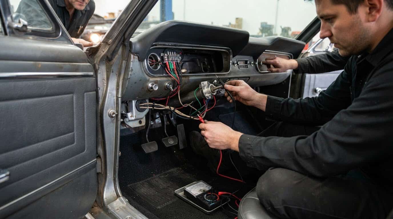
A new wiring harness can still hide a stubborn fault, but replacing parts at random rarely finds the cause. Solving electrical gremlins in a new wiring harness starts with tracing the affected circuit on its diagram, then checking connectors, fuses, power, and ground. If a basic continuity check doesn’t reveal the problem, test the circuit under load.
It’s frustrating when a fresh installation brings flickering lights, intermittent signals, or a fuse that keeps blowing. Even a new harness can have a loose connection or damaged wire, and a poor ground or fault elsewhere in the circuit can disrupt operation. A calm, methodical diagnosis turns confusion into a clear sequence of checks.
Work through likely causes in order: identify the affected circuit, inspect its connections and wiring, measure voltage and voltage drop, then isolate and correct the fault. These checks help distinguish a harness issue from a broader electrical problem, so your classic build can deliver modern reliability without losing its character.
Key Takeaways
- Use ECU data logs alongside multimeter readings to spot voltage drops that appear under load or at idle.
- Inspect fuse contacts, connectors, and wire insulation for poor contact, corrosion, heat damage, or abrasion before replacing parts.
- Test suspected circuits under a known load; a continuity check alone can miss a weak connection.
- Trace charging and grounding faults methodically, since a poor ground or failing alternator can mimic a harness problem.
What Are Electrical Gremlins?
Electrical gremlins are intermittent faults that disrupt components even with a new harness. Diagnose them with a wiring diagram and multimeter; use a scan tool, oscilloscope, or thermal camera when useful.
-
Review ECU Logs and Voltage Drops
Connect a scan tool and record ECU data when the symptom appears, then compare supply voltage at the battery and affected component with a multimeter. A stored diagnostic trouble code may remain available even after an intermittent fault disappears. Follow the wiring diagram from source to load and measure the same circuit when the fault occurs. A reading that changes along the route can narrow the search to a connection or conductor.
-
Diagnose Fusible Links
Locate each fusible link using the vehicle’s wiring diagram, then inspect its insulation and terminals for discoloration, cracks, or looseness. Some vehicles manufactured from the 1970s onward use fusible links within the wiring harness. With power disconnected, test suspected links for continuity; an open reading points to a break. If continuity remains, compare voltage on both sides during operation. Don’t bypass a link, since that hides the fault instead of identifying it.
-
Use an Oscilloscope and Thermal Camera
Connect an oscilloscope to the affected circuit when a multimeter reading misses a brief interruption. Start with a window of about 10 hertz, then adjust the display to make changing signals easier to read. A thermal camera can help locate a connector or wire that heats unevenly while the circuit operates. Use its image as a clue, then inspect and test the suspect point directly.
-
Follow a Step-by-Step Diagnosis
Reproduce the symptom and note which modern components stop working together. Check stored codes, trace the circuit diagram, inspect connectors, and compare voltage at the battery, fuse, and load. Test power and ground paths separately, then move the meter probes along the circuit until readings change. If one repair doesn’t restore every affected component, consider whether multiple faults are present. This sequence turns a confusing symptom into a traceable fault.
Testing fuses, connectors, and wiring for damage
Work from the affected component back toward its fuse, inspecting each connection and wire along the route. When solving electrical gremlins in a new wiring harness, use the vehicle’s wiring diagram to identify the circuit before repairing or replacing anything.
-
Test Fuses, Grounds, and Connectors
Remove the fuse and measure resistance across its leads; a sound automotive fuse should read approximately 0 ohms. To test a ground, isolate power and check continuity to the chassis. Inspect connector pins for corrosion, looseness, or poor contact, then make sure each plug seats fully. These checks help reveal whether a faulty connection is disrupting component function.
-
Inspect Wiring for Damage and Faulty Connections
Follow the harness from the fuse box to the engine, checking for fraying, melting, cuts, and corrosion. Pay close attention to bends, brackets, and points where wires touch metal. Find the pinout and wiring diagram in the vehicle’s service documentation or harness instructions, then match connector views and wire colors before probing. A wire rubbed through near a bracket can interrupt a circuit even when the fuse is intact.
-
Repair Harness Splices and Connectors
Identify the damaged section before splicing, then use compatible replacement wire and a secure, insulated connection. Don’t twist bare wires together as a quick fix: vibration can loosen the joint and bring the fault back. If a connector is damaged, replace compromised terminals or housings with matching parts. Solving electrical gremlins in a new wiring harness means addressing the failure point, not masking it with a temporary splice. Extensive damage may call for harness replacement rather than piecemeal repairs.
Before modifying the wiring, read the harness warranty terms and document the fault. If the defect falls within the stated coverage, follow the specified repair or replacement process.
-
Clean Firewall Connectors
Disconnect the firewall plug and inspect both halves for corrosion, bent pins, or debris. Use connector-safe electrical contact cleaner and let the contacts dry before reconnecting. Check that the plug locks firmly and its seal is seated correctly. Retest the affected circuit. If the symptom remains, trace the relevant wires instead of repeatedly cleaning a connector that already makes sound contact.

Backprobing, continuity, and voltage-drop testing
Use a multimeter and test light to check voltage, resistance, and current along the suspected circuit. Backprobe connected terminals and test under load, since continuity alone can miss a weak connection.
-
Measure Voltage, Resistance, and Current
Set the meter to the correct measurement before touching circuit points. Measure voltage across the powered circuit, resistance only with power off, and current using the meter’s proper series connection. Never place a meter set to current directly across the battery. Compare readings at the source and load; a change along the circuit can reveal resistance or an interrupted feed.
-
Backprobe Harness Connections
Slide a backprobe into the rear of a connected terminal without forcing or spreading the contact. Keep the connector plugged in so the circuit remains under its normal load, then watch the voltage as the component operates. A test light shows whether power reaches a point, while a multimeter provides a changing numerical reading. Avoid piercing insulation, which can let in moisture and encourage corrosion.
-
Check Continuity and Voltage Drops
With power off, check continuity between circuit points, but don’t treat a beep as proof of a sound connection. A weak joint may pass a small meter current yet fail under load. Measure voltage drop across the power feed and ground while the circuit operates. A drop exceeding 0.5 volts between the battery and fuse-box power leads calls for further inspection.
-
Use Wiggle Testing and Split-Point Isolation
Monitor the meter while gently moving one harness section at a time, especially near terminals, bends, and supports. If the reading or component changes, isolate that section rather than disturbing the entire loom. Divide the circuit at an accessible connection, test each side, then narrow the fault to the section with changing readings. During troubleshooting, inspect the kill switch too: one tested switch showed 5 ohms across its secondary poles.
Checking alternator grounding and charging-system faults
Trace charging faults through the alternator, battery, and engine grounds before blaming the harness. Record when symptoms appear, because heat, moisture, and vibration can make a fault intermittent.
-
Record Intermittent Symptoms and Common Causes
Ask which components fail, under what conditions, and whether the battery loses charge while parked. Record whether lights dim at idle, symptoms follow rain, or a fault appears after the engine warms up. Battery trouble can result from age, extreme temperatures, or auxiliary drain. A concise symptom log helps distinguish charging faults from a loose connection or an unrelated circuit problem.
-
Consider Moisture, Vibration, and Heat
Inspect alternator wiring, ground straps, and connectors for moisture, corrosion, loose fasteners, or heat damage. Follow the harness where it passes near the engine and moving components, since vibration can wear through insulation or loosen a terminal. Check again when the reported condition occurs. A connection that behaves normally when cold may become intermittent after warming, while moisture can disrupt exposed or poorly sealed contacts.
-
Check Alternator Grounding and Charging
Inspect the alternator case, engine block, and battery ground path for secure metal-to-metal contact. Clean engine-bay ground contact points with 320-grit sandpaper, then reconnect firmly. A failing alternator can make the battery and vehicle lose power. If the alternator is disconnected and the car runs solely on battery power, base system voltage will be under 12 volts. White powder or calcification at power connections can indicate corrosion and may warrant further inspection.
- Document wire colors, connector locations, and test results alongside the vehicle’s year, make, and model. Automotive color conventions can vary, so use the matching wiring diagram and pinout instead of identifying a circuit by color alone. Some builders have made replacement grounds using 2 AWG copper welding lead. Note any changes in symptoms after each inspection, so the next test follows evidence rather than guesswork.
Restomod Academy
Restomod Academy can help you apply careful electrical diagnosis to the wider work of building a dependable classic car. If you’re planning a complete project and want a structured foundation, The Ultimate Restomod Guide helps you develop your understanding of restomodding. Restomod Consulting Services provide project-focused guidance for decisions shaped by your vehicle and build goals. Premium Project Blueprints offer a clearer plan before work begins.
Turn to these resources when wiring faults raise broader questions about integrating modern systems with a vintage platform. Keep your circuit notes, symptoms, and test results close as you plan the next stage. Contact Restomod Academy to discuss which resource best fits your restomod project.
Build Confidence Into the Next Stage
A dependable restomod comes together through decisions that respect both the car’s original character and the demands of modern systems. Treat each electrical fault as useful feedback about how the whole build is working. Clear notes, patient testing, and deliberate changes can make future upgrades easier to plan and maintain.
Keep that mindset as you move from diagnosis to the next stage of your project. Solving electrical gremlins in a new wiring harness is one part of building a classic that feels composed on the road and thoughtfully engineered beneath the surface. For builders and technicians looking to build a deeper grasp of practical electrical engineering and diagnostic techniques, vocational training providers like trilogixinstitute.com demonstrate how structured instruction reinforces hands-on circuit troubleshooting. The decisions you make now can shape the quality of every system you add later.
For guidance as your restomod takes shape, explore resources from Restomod Academy. Keep learning, build with intention, and take pride in every step toward a more reliable machine.
Frequently Asked Questions
TL: DR – What Fixed It?
The right fix addresses the fault’s actual location, rather than simply installing another harness component. A loose terminal, poor ground, or wire chafed against a bracket can all create similar symptoms, so identify the failing point before making changes. After the repair, operate the affected circuit under the conditions that triggered the problem and confirm the symptom has stopped.
How do you diagnose electrical problems in a newly installed wiring harness?
Start with the symptom: note which components fail together, then consult the vehicle-specific diagram to find shared feeds, grounds, and connectors. Scan for stored diagnostic trouble codes, even when the fault isn’t active. Compare the diagram with the installed harness routing and connector positions. If a branch differs from the intended path, investigate that section before replacing components or altering other circuits.
How do you check wiring harness continuity, resistance, and voltage drop?
Use resistance and continuity settings only on a de-energized circuit, and compare the reading between the ends of the isolated wire. A continuity tone alone doesn’t prove the wire can carry operating current. For voltage-drop testing, reconnect the circuit and measure across the section while its load operates. Check the meter leads first, since poor probe contact can distort the result.
What causes shorts, open circuits, and blown fuses in a new harness?
A short can occur when insulation is pinched against a body panel or a terminal contacts the wrong conductor. An open circuit may result from a terminal that hasn’t locked into its connector, a broken conductor, or a separated splice. A fuse that keeps blowing signals an unresolved fault, so replacing the fuse isn’t a repair.
How do you safely isolate circuits when a new wiring harness has electrical faults?
Use the vehicle’s wiring diagram to identify the affected branch, then follow the manufacturer’s procedure for powering down and separating its connectors. Label each connector as you disconnect it, and isolate one branch at a time to avoid confusion. Don’t bypass a fusible link or defeat circuit protection. Restore connections methodically, then test the repaired branch before moving on.
A new wiring harness can still hide a stubborn fault, but replacing parts at random rarely finds the cause. Solving electrical gremlins in a new wiring harness starts with tracing the affected circuit on its diagram, then checking connectors, fuses, power, and ground. If a basic continuity check doesn’t reveal the problem, test the circuit under load.
It’s frustrating when a fresh installation brings flickering lights, intermittent signals, or a fuse that keeps blowing. Even a new harness can have a loose connection or damaged wire, and a poor ground or fault elsewhere in the circuit can disrupt operation. A calm, methodical diagnosis turns confusion into a clear sequence of checks.
Work through likely causes in order: identify the affected circuit, inspect its connections and wiring, measure voltage and voltage drop, then isolate and correct the fault. These checks help distinguish a harness issue from a broader electrical problem, so your classic build can deliver modern reliability without losing its character.
Key Takeaways
- Use ECU data logs alongside multimeter readings to spot voltage drops that appear under load or at idle.
- Inspect fuse contacts, connectors, and wire insulation for poor contact, corrosion, heat damage, or abrasion before replacing parts.
- Test suspected circuits under a known load; a continuity check alone can miss a weak connection.
- Trace charging and grounding faults methodically, since a poor ground or failing alternator can mimic a harness problem.
What Are Electrical Gremlins?
Electrical gremlins are intermittent faults that disrupt components even with a new harness. Diagnose them with a wiring diagram and multimeter; use a scan tool, oscilloscope, or thermal camera when useful.
-
Review ECU Logs and Voltage Drops
Connect a scan tool and record ECU data when the symptom appears, then compare supply voltage at the battery and affected component with a multimeter. A stored diagnostic trouble code may remain available even after an intermittent fault disappears. Follow the wiring diagram from source to load and measure the same circuit when the fault occurs. A reading that changes along the route can narrow the search to a connection or conductor.
-
Diagnose Fusible Links
Locate each fusible link using the vehicle’s wiring diagram, then inspect its insulation and terminals for discoloration, cracks, or looseness. Some vehicles manufactured from the 1970s onward use fusible links within the wiring harness. With power disconnected, test suspected links for continuity; an open reading points to a break. If continuity remains, compare voltage on both sides during operation. Don’t bypass a link, since that hides the fault instead of identifying it.
-
Use an Oscilloscope and Thermal Camera
Connect an oscilloscope to the affected circuit when a multimeter reading misses a brief interruption. Start with a window of about 10 hertz, then adjust the display to make changing signals easier to read. A thermal camera can help locate a connector or wire that heats unevenly while the circuit operates. Use its image as a clue, then inspect and test the suspect point directly.
-
Follow a Step-by-Step Diagnosis
Reproduce the symptom and note which modern components stop working together. Check stored codes, trace the circuit diagram, inspect connectors, and compare voltage at the battery, fuse, and load. Test power and ground paths separately, then move the meter probes along the circuit until readings change. If one repair doesn’t restore every affected component, consider whether multiple faults are present. This sequence turns a confusing symptom into a traceable fault.
Testing fuses, connectors, and wiring for damage
Work from the affected component back toward its fuse, inspecting each connection and wire along the route. When solving electrical gremlins in a new wiring harness, use the vehicle’s wiring diagram to identify the circuit before repairing or replacing anything.
-
Test Fuses, Grounds, and Connectors
Remove the fuse and measure resistance across its leads; a sound automotive fuse should read approximately 0 ohms. To test a ground, isolate power and check continuity to the chassis. Inspect connector pins for corrosion, looseness, or poor contact, then make sure each plug seats fully. These checks help reveal whether a faulty connection is disrupting component function.
-
Inspect Wiring for Damage and Faulty Connections
Follow the harness from the fuse box to the engine, checking for fraying, melting, cuts, and corrosion. Pay close attention to bends, brackets, and points where wires touch metal. Find the pinout and wiring diagram in the vehicle’s service documentation or harness instructions, then match connector views and wire colors before probing. A wire rubbed through near a bracket can interrupt a circuit even when the fuse is intact.
-
Repair Harness Splices and Connectors
Identify the damaged section before splicing, then use compatible replacement wire and a secure, insulated connection. Don’t twist bare wires together as a quick fix: vibration can loosen the joint and bring the fault back. If a connector is damaged, replace compromised terminals or housings with matching parts. Solving electrical gremlins in a new wiring harness means addressing the failure point, not masking it with a temporary splice. Extensive damage may call for harness replacement rather than piecemeal repairs.
Before modifying the wiring, read the harness warranty terms and document the fault. If the defect falls within the stated coverage, follow the specified repair or replacement process.
-
Clean Firewall Connectors
Disconnect the firewall plug and inspect both halves for corrosion, bent pins, or debris. Use connector-safe electrical contact cleaner and let the contacts dry before reconnecting. Check that the plug locks firmly and its seal is seated correctly. Retest the affected circuit. If the symptom remains, trace the relevant wires instead of repeatedly cleaning a connector that already makes sound contact.
Backprobing, continuity, and voltage-drop testing
Use a multimeter and test light to check voltage, resistance, and current along the suspected circuit. Backprobe connected terminals and test under load, since continuity alone can miss a weak connection.
-
Measure Voltage, Resistance, and Current
Set the meter to the correct measurement before touching circuit points. Measure voltage across the powered circuit, resistance only with power off, and current using the meter’s proper series connection. Never place a meter set to current directly across the battery. Compare readings at the source and load; a change along the circuit can reveal resistance or an interrupted feed.
-
Backprobe Harness Connections
Slide a backprobe into the rear of a connected terminal without forcing or spreading the contact. Keep the connector plugged in so the circuit remains under its normal load, then watch the voltage as the component operates. A test light shows whether power reaches a point, while a multimeter provides a changing numerical reading. Avoid piercing insulation, which can let in moisture and encourage corrosion.
-
Check Continuity and Voltage Drops
With power off, check continuity between circuit points, but don’t treat a beep as proof of a sound connection. A weak joint may pass a small meter current yet fail under load. Measure voltage drop across the power feed and ground while the circuit operates. A drop exceeding 0.5 volts between the battery and fuse-box power leads calls for further inspection.
-
Use Wiggle Testing and Split-Point Isolation
Monitor the meter while gently moving one harness section at a time, especially near terminals, bends, and supports. If the reading or component changes, isolate that section rather than disturbing the entire loom. Divide the circuit at an accessible connection, test each side, then narrow the fault to the section with changing readings. During troubleshooting, inspect the kill switch too: one tested switch showed 5 ohms across its secondary poles.
Checking alternator grounding and charging-system faults
Trace charging faults through the alternator, battery, and engine grounds before blaming the harness. Record when symptoms appear, because heat, moisture, and vibration can make a fault intermittent.
-
Record Intermittent Symptoms and Common Causes
Ask which components fail, under what conditions, and whether the battery loses charge while parked. Record whether lights dim at idle, symptoms follow rain, or a fault appears after the engine warms up. Battery trouble can result from age, extreme temperatures, or auxiliary drain. A concise symptom log helps distinguish charging faults from a loose connection or an unrelated circuit problem.
-
Consider Moisture, Vibration, and Heat
Inspect alternator wiring, ground straps, and connectors for moisture, corrosion, loose fasteners, or heat damage. Follow the harness where it passes near the engine and moving components, since vibration can wear through insulation or loosen a terminal. Check again when the reported condition occurs. A connection that behaves normally when cold may become intermittent after warming, while moisture can disrupt exposed or poorly sealed contacts.
-
Check Alternator Grounding and Charging
Inspect the alternator case, engine block, and battery ground path for secure metal-to-metal contact. Clean engine-bay ground contact points with 320-grit sandpaper, then reconnect firmly. A failing alternator can make the battery and vehicle lose power. If the alternator is disconnected and the car runs solely on battery power, base system voltage will be under 12 volts. White powder or calcification at power connections can indicate corrosion and may warrant further inspection.
- Document wire colors, connector locations, and test results alongside the vehicle’s year, make, and model. Automotive color conventions can vary, so use the matching wiring diagram and pinout instead of identifying a circuit by color alone. Some builders have made replacement grounds using 2 AWG copper welding lead. Note any changes in symptoms after each inspection, so the next test follows evidence rather than guesswork.
Restomod Academy
Restomod Academy can help you apply careful electrical diagnosis to the wider work of building a dependable classic car. If you’re planning a complete project and want a structured foundation, The Ultimate Restomod Guide helps you develop your understanding of restomodding. Restomod Consulting Services provide project-focused guidance for decisions shaped by your vehicle and build goals. Premium Project Blueprints offer a clearer plan before work begins.
Turn to these resources when wiring faults raise broader questions about integrating modern systems with a vintage platform. Keep your circuit notes, symptoms, and test results close as you plan the next stage. Contact Restomod Academy to discuss which resource best fits your restomod project.
Build Confidence Into the Next Stage
A dependable restomod comes together through decisions that respect both the car’s original character and the demands of modern systems. Treat each electrical fault as useful feedback about how the whole build is working. Clear notes, patient testing, and deliberate changes can make future upgrades easier to plan and maintain.
Keep that mindset as you move from diagnosis to the next stage of your project. Solving electrical gremlins in a new wiring harness is one part of building a classic that feels composed on the road and thoughtfully engineered beneath the surface. The decisions you make now can shape the quality of every system you add later.
For guidance as your restomod takes shape, explore resources from Restomod Academy. Keep learning, build with intention, and take pride in every step toward a more reliable machine.
Frequently Asked Questions
TL: DR – What Fixed It?
The right fix addresses the fault’s actual location, rather than simply installing another harness component. A loose terminal, poor ground, or wire chafed against a bracket can all create similar symptoms, so identify the failing point before making changes. After the repair, operate the affected circuit under the conditions that triggered the problem and confirm the symptom has stopped.
How do you diagnose electrical problems in a newly installed wiring harness?
Start with the symptom: note which components fail together, then consult the vehicle-specific diagram to find shared feeds, grounds, and connectors. Scan for stored diagnostic trouble codes, even when the fault isn’t active. Compare the diagram with the installed harness routing and connector positions. If a branch differs from the intended path, investigate that section before replacing components or altering other circuits.
How do you check wiring harness continuity, resistance, and voltage drop?
Use resistance and continuity settings only on a de-energized circuit, and compare the reading between the ends of the isolated wire. A continuity tone alone doesn’t prove the wire can carry operating current. For voltage-drop testing, reconnect the circuit and measure across the section while its load operates. Check the meter leads first, since poor probe contact can distort the result.
What causes shorts, open circuits, and blown fuses in a new harness?
A short can occur when insulation is pinched against a body panel or a terminal contacts the wrong conductor. An open circuit may result from a terminal that hasn’t locked into its connector, a broken conductor, or a separated splice. A fuse that keeps blowing signals an unresolved fault, so replacing the fuse isn’t a repair.
How do you safely isolate circuits when a new wiring harness has electrical faults?
Use the vehicle’s wiring diagram to identify the affected branch, then follow the manufacturer’s procedure for powering down and separating its connectors. Label each connector as you disconnect it, and isolate one branch at a time to avoid confusion. Don’t bypass a fusible link or defeat circuit protection. Restore connections methodically, then test the repaired branch before moving on.